Turbo Bass circuit diagram

More about Turbo Bass »
Eight Sound Effects Generator circuit diagram
Here teh circuit diagram of eight sound effects. The circuit will generate 8 type of sound effect, amplify the audio signal, so you will hear the sound directly from the speaker.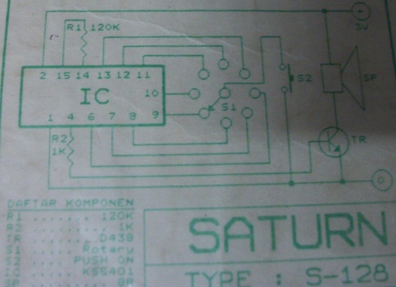

Six LED Stereo VU Display circuit diagram
The following circuit is six LED stereo VU display diagram which build using Dot/Bar Display Driver IC LM3915. This VU disply should be connected before amplifier module circuit. You may connect this circuit at pre-amp output, tone control input/output or equaliser input/output.
The LM3915 is a monolithic integrated circuit that senses analog voltage levels and drives ten LEDs, LCDs or vacuum fluorescent displays, providing a logarithmic 3 dB/step analog display. One pin changes the display from a bar graph to a moving dot display. LED current drive is regulated and programmable, eliminating the need for current limiting resistors.
More about Six LED Stereo VU Display »
Hi-Fi Tone Control circuit diagram
This is a cheap high fidelity (hi-fi) tone control circuit. The schematic is one channel (mono) tone control, build the similar circuit will make it become stereo.
More about Hi-Fi Tone Control »
Audio Mixer + VU Meter circuit diagram
This is audio mixer circuit. The circuit is for one channel input, if you need, for example 5 channel mixer, then you need to build 5 similar circuits.Schematic diagram:

More about Audio Mixer + VU Meter »
Echo Chamber circuit diagram
Below circuit is an echo chamber circuit which can be used for smoothing your voice from the microphone. This circuit may used for any kind of audio signal (microphone, radio, mp3 player, etc).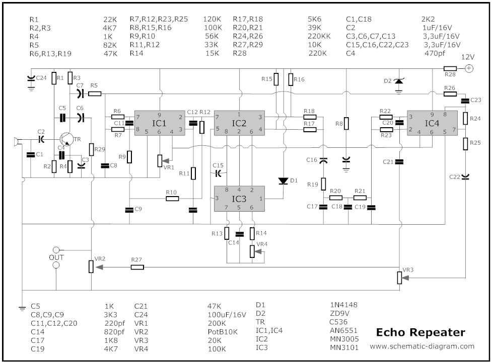

More about Echo Chamber »


Tidak ada komentar:
Posting Komentar